
Product selection & application
How to Thread a Wire Buckle for Composite Strap
These photographs show a composite strap, a wire buckle and a manual tensioner used together on a demonstration frame. Use the sequence to understand the components and the joint. Confirm the exact buckle orientation, threading and tool procedure for your selected system before applying it to cargo.
Check the matched components first
Use the specified composite strap and wire-buckle combination, with an undamaged tensioner that supports the selected strap. Inspect the strap and buckle, prepare any required edge protection and follow the equipment instructions and site procedure. The frame in these photographs is a demonstration setup, not a load-restraint design.
1. Form the first strap loop
Fold the strap back to make a loop, keeping the material flat. Allow sufficient free length for threading and handling according to the approved procedure for the buckle.

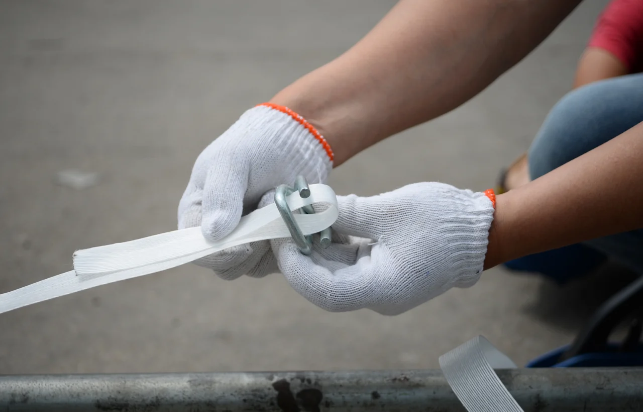
2. Place the loop through the buckle and around its leg
The close-ups show the folded loop being introduced into the buckle opening and seated around a buckle leg. Pay attention to the buckle orientation and the way the strap folds back over itself. Keep the strap flat rather than rolled or twisted.

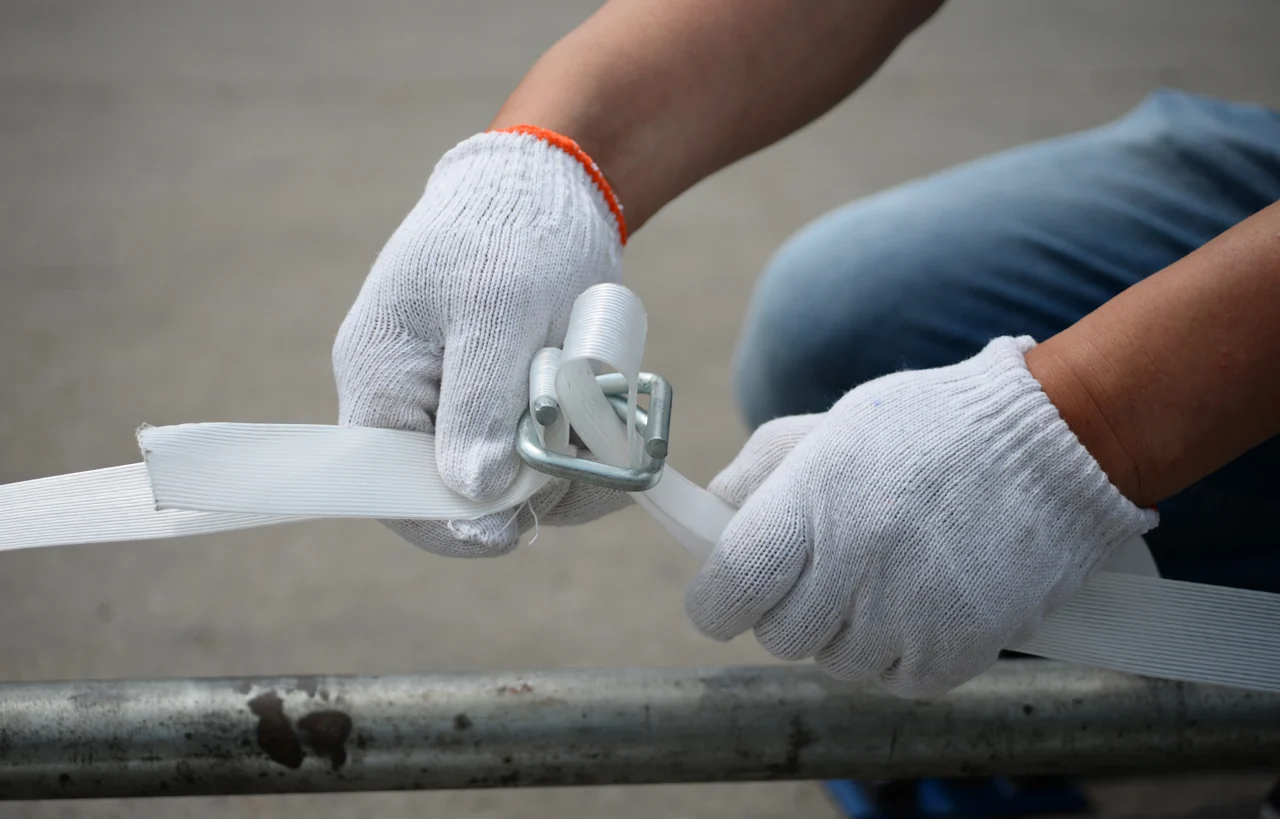
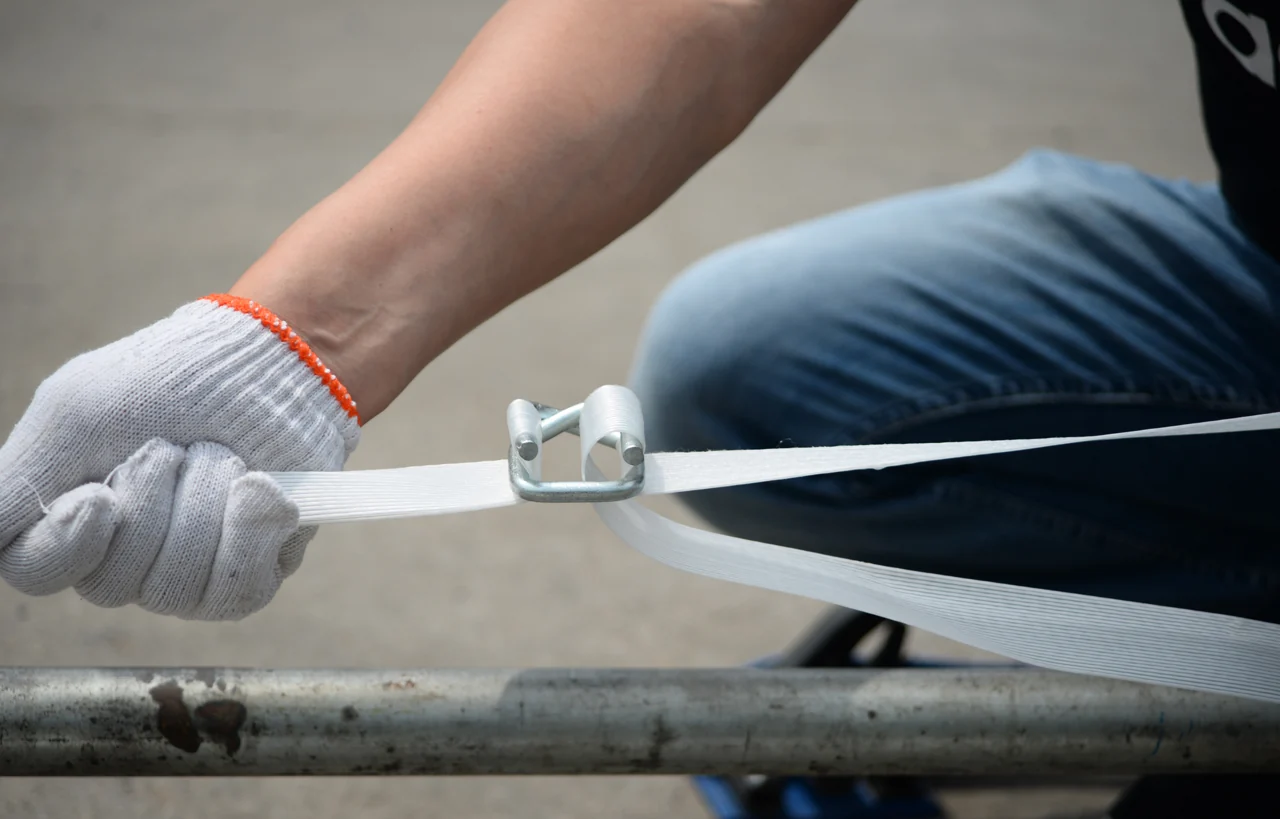
3. Thread the returning end and remove slack
Bring the strap around the package or demonstration frame, then form and seat the returning loop on the other buckle leg according to the specified threading path. The photographs show both loops before and after hand tightening. Check that both sides are correctly seated and the strap runs flat.
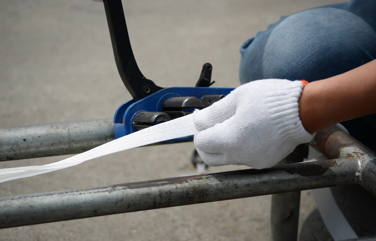
4. Position the manual tensioner
The stationary strap and the free end have separate paths through the tool. Place them in the clamp, guide, cutter and winding mechanism as required by the tool’s manual. Keep hands away from moving parts and confirm the strap is seated before applying tension.
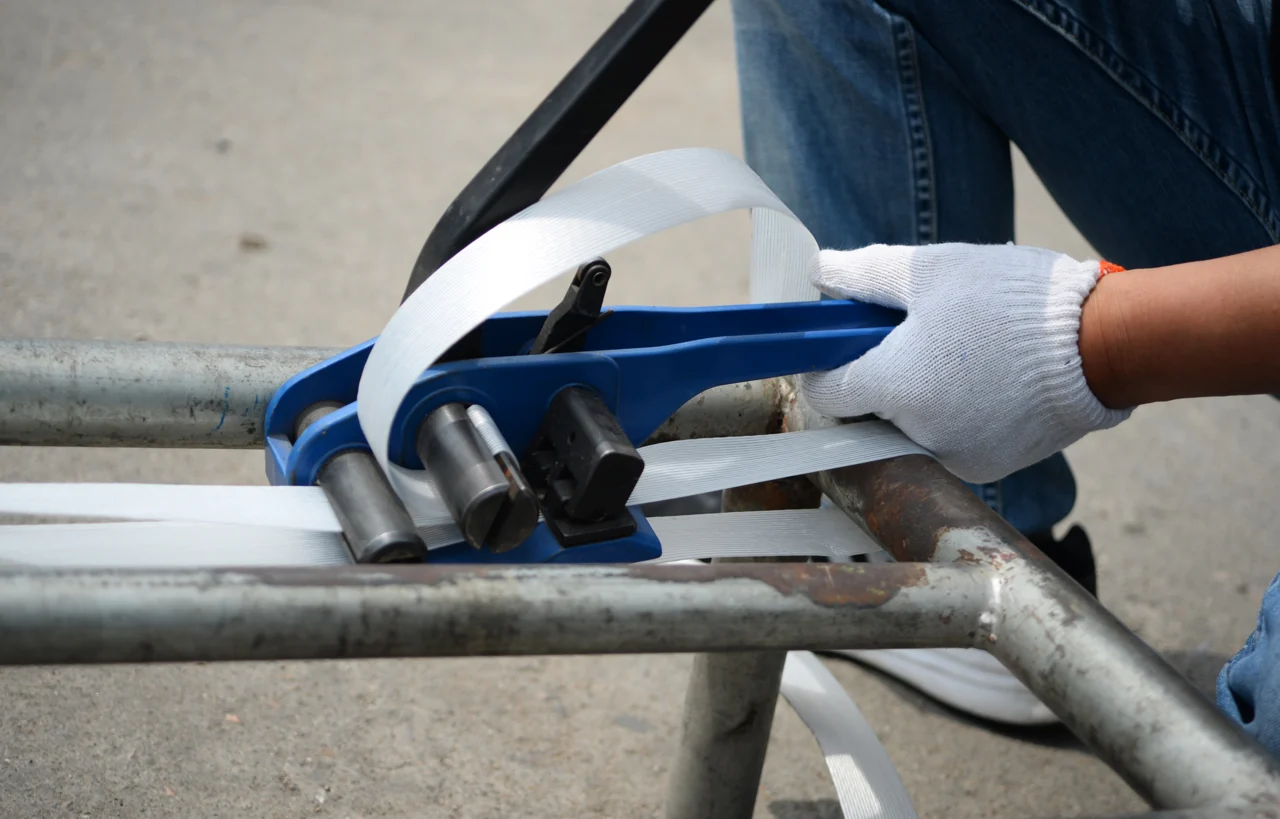
5. Tension, finish and inspect the joint
Operate, cut and release the tool using its specified procedure. Do not over-tension the package or use breaking-strength figures as a tension setting. After removing the tool, inspect loop seating, strap alignment, edge contact and the finished joint. A photograph of a completed joint does not confirm the restraint capacity of a shipment.
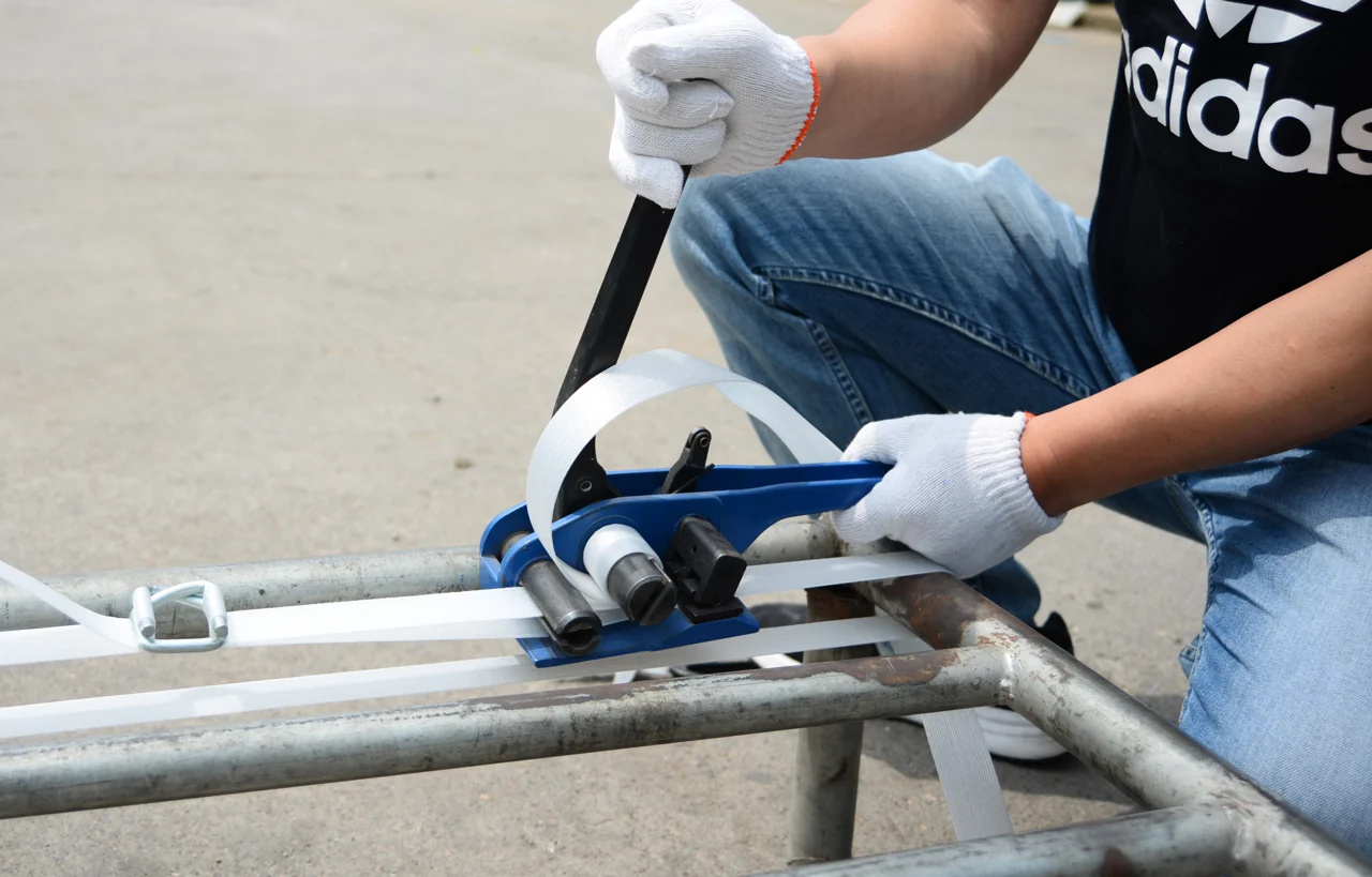
Common issues to check
- Twisted strap or loops that are not fully seated.
- A buckle size or finish that has not been confirmed for the strap.
- Strap loaded into the wrong tool path or a tool outside its supported range.
- Sharp contact edges, damaged material or uncontrolled release.
If you need help identifying a combination, send photographs of your strap, buckle and tensioner together with their model numbers. We can review product compatibility before preparing a quotation.